S.H.A.D.O.W Controller
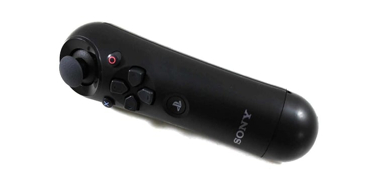
S.H.A.D.O.W. (Small Handheld Arduino Droid Operating Wand) If you don't want to use a big chunky RC controller but instead want to use a small hand held controller that keeps more of the magic for people interacting with your Droid then the S.H.A.D.O.W system is for you ! This method allows you to control your droid with one of two common options: 1. PS3 Move Movement Controller ( the one without the ball on top ) 2. Dedicated RC controller with a similar form and function as the PS3 Move
- Setup SHADOW with Arduino IDE
- Assemble the stack
- Sound Boards
- Control Map
- USB Host Shield Troubleshooting
- TL:DR Checklist
Setup SHADOW with Arduino IDE
Getting started
So, you have the Arduino (Uno, Mega), USB Host Shield, USB Bluetooth 4.0 dongle, USB-A to USB-Mini wire, and PS3 Move Navigation controller but don't know what to do next ? That's easy just follow along with this guide.
Arduino IDE Setup
Before going further, please make s ure you've downloaded and installed the Arduino IDE .
After it is installed, it's time to grab the SHADOW Arduino Sketch from Github here and then unzip it, the resulting folder will probably be called "SHADOW-master".
- Open the Arduino IDE to set up the config folders and accept any access requests and then close it again.
- Go to the "libraries" folder in the extracted SHADOW-master folder and copy the following library folders into the "Arduino/libraries" folder that the IDE created. This will be in "Documents" (Linux / OSX) or "My Documents" (Windows) by default.
- USB_Host_Shield - Always use this
- MP3Trigger (For the Sparkfun MP3 Trigger)
- serMP3 (For the MdFly MP3 board)
- Start the Arduino IDE, or restart if if you didn't before copying the libraries, to make sure they get loaded.
- Go to file -> open and go into the extracted SHADOW-master folder from earlier. There is a "Shadow" folder underneath, next to the "libraries" folder. Select and open the "Shadow.ino" file.
Now you have set up the IDE and are now prepared to use the Sketch.
Connect to your board
For this step you will need to have assembled your Arduino + USB Shield like below.
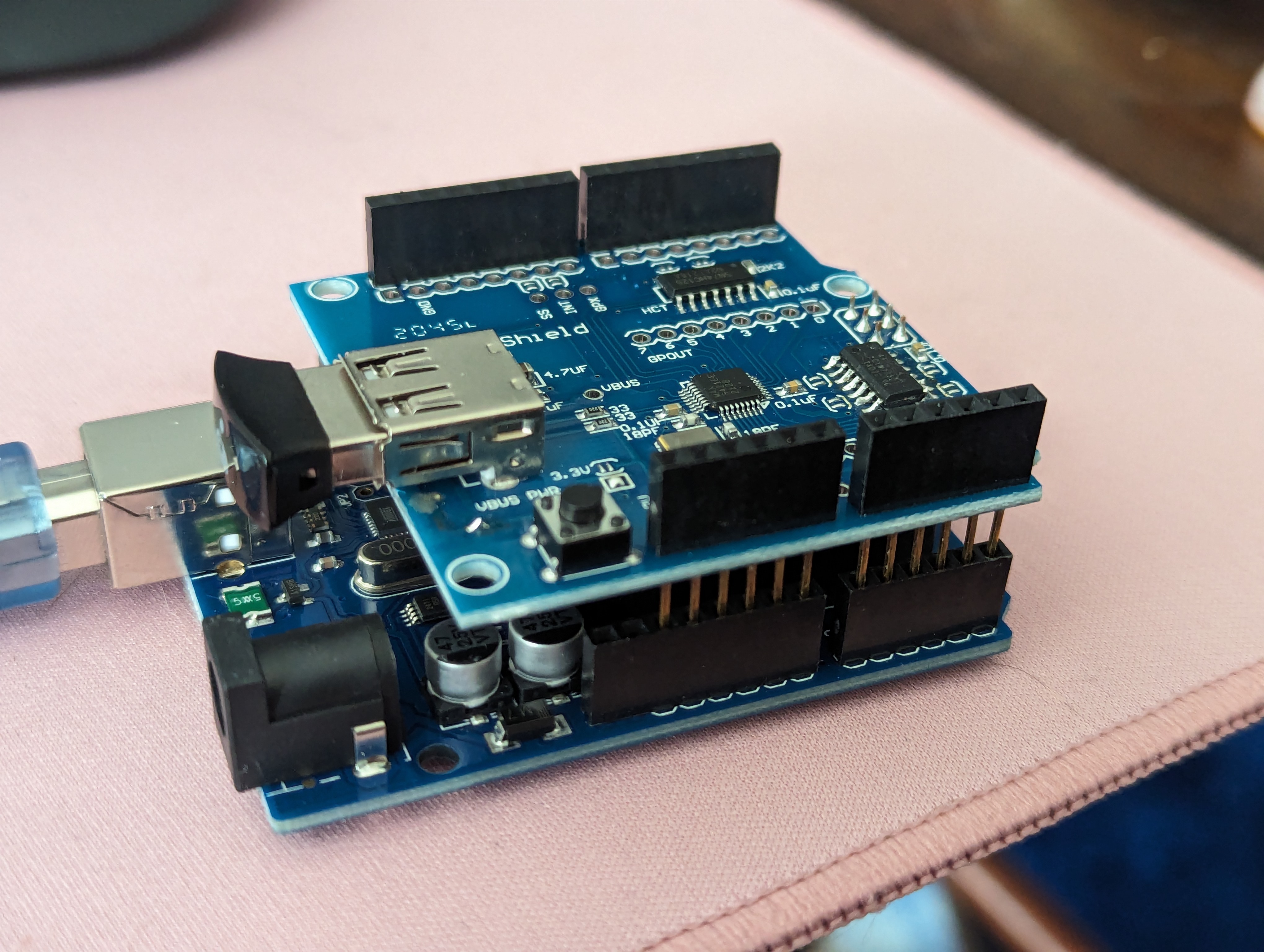
Plug your Arduino into your computer with a USB-A or C to your computer and USB-B to your Arduino cable and go back to your Arduino IDE for the next steps.
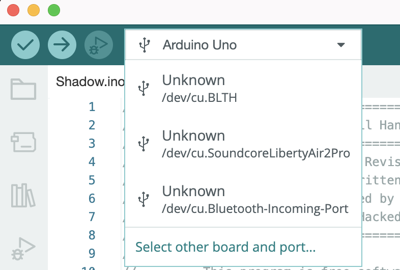
The Arduino IDE may have automatically detected and connected to your Arduino when you connected it. If not, you can manually connect within the IDE.
The dropdown box near the top of the editor (below) will show your options, select the correct connection. If somehow it's not showing the correct Arduino board type, you can now click on Tools -> Board -> Arduino AVR Boards -> select the correct board.
Upload the Sketch
Now that you have connected the board to the IDE, it's time to actually upload the sketch.
For this step, you should have your Arduino connected to the IDE, and the USB Adapter should be plugged into the USB Host Shield.
First, let's use the Verify function to make sure the code is ready to upload to the Arduino.
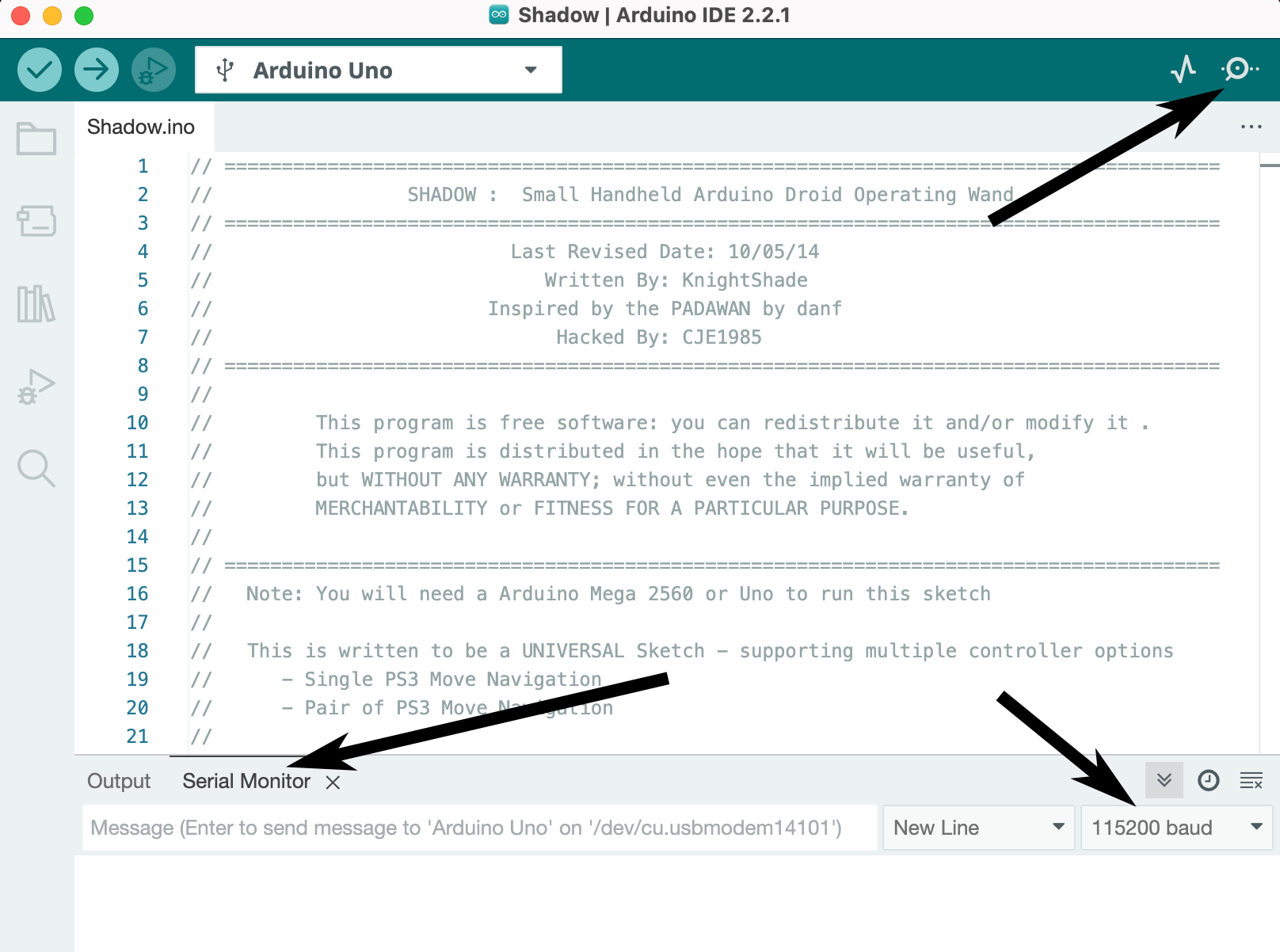
Click on the round Check mark button  or go to Sketch -> Verify/Compile to verify the Sketch and Libraries are ready for use. If you don't see any errors, all is well!
Next, set up the IDE so you can see what is happening on your Arduino.
Click on the "Serial Monitor" button  in the upper right and a panel will open at the bottom of the IDE with a "Serial Monitor" tab.
On the right-side of the "Serial Monitor" you need to set the "baud" rate to "115200". If you don't the board and your computer won't be able to talk to each other properly when you upload the Sketch. See below.
Now that you are ready, it's time to upload the sketch.
Click on the round "Upload" button  in the upper left that looks like an arrow pointing right (towards the Arduino).
Now, on to connecting your controller!
Connect your controller
Now for the part you've been waiting for, putting it all together and connecting your controller!
For this section, you'll need the USB to USB-mini cable and PS3 Move controller in addition to your Arduino+Shield.
After uploading the sketch, your "Serial Monitor" should have output that looks like this.
Bluetooth Library Started
MDFly MP3 Initialized
MSE Drive Running
Bluetooth Dongle Initialized
No response to HCI Reset
HCI Reset complete
Write class of device
Local Bluetooth Address: 00:1D:5D:DA:71:1B
Wait For Incoming Connection RequestWhat comes next is a specific order of operations so please follow them exactly as below.
- Remove the USB Bluetooth Adapter, do not reset or unplug the Arduino board
- Plug the PS3 Move controller into the USB Host Shield
-
Expect similar output in Monitor console
Navigation Controller Connected Bluetooth Address was set to: 00:1D:5D:DA:71:1B
-
- Unplug the PS3 Move controller
- Plug in the USB Bluetooth Adapter
- Example Monitor output
Bluetooth Dongle Initialized No response to HCI Reset HCI Reset complete Write class of device Local Bluetooth Address: 00:1D:5D:DA:71:1B Wait For Incoming Connection Request
- Example Monitor output
- Press the Playstation button in the middle of the controller below the D-Pad.
- The red light on the controller will flash while it's waiting to connect to the Bluetooth adapter.
- The red light will be solid red when it successfully connects to your board.
- Example of successful connection
Navigation Controller Connected Bluetooth Address was set to: 00:1D:5D:DA:71:1B Bluetooth Dongle Initialized No response to HCI Reset HCI Reset complete Write class of device Local Bluetooth Address: 00:1D:5D:DA:71:1B Wait For Incoming Connection Request Gamepad is connecting Incoming Connection Request Remote Name: Navigation Controller Connected to Device: 04:76:6E:32:BD:C5 HID Control Incoming Connection Request HID Control Successfully Configured HID Interrupt Incoming Connection Request HID Interrupt Successfully Configured Wait For Incoming Connection Request Navigation Controller Enabled
- Grab the Navigation Controller MAC address from the output
- Look for the "Connected to Device:" value like "04:76:6E:32:BD:C5" from the example.
Wait For Incoming Connection Request Gamepad is connecting Incoming Connection Request Remote Name: Navigation Controller Connected to Device: 04:76:6E:32:BD:C5
- Look for the "Connected to Device:" value like "04:76:6E:32:BD:C5" from the example.
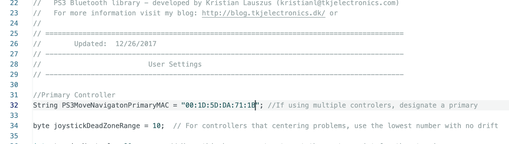
- Go to the IDE text editor and find the "PS3MoveNavigatonPrimaryMAC" variable and replace the value with the Controller MAC address you copied from the output in step 6.
- Save the Sketch (ctrl+s, or cmd+s).
- Upload the updated Sketch to the Arduino using the Upload function
 . This step is important since this tells SHADOW what controller to listen to and accept actions from.
Now your board is ready for final assembly and connecting your board
Assemble the stack
Complete the Sandwich
Now that you have the Arduino and USB Host shield set up, the next step is to start putting the rest of it together!
Unplug the Arduino if it's still plugged in to your computer then put your Shadow Master Shield onto it so the order of your boards should be:
- Arduino (bottom)
- USB Host Shield (middle)
- SHADOW Master (top)
Replace the ESC for your car
SHADOW doesn't like to work with the stock ESC from Traxxas. Luckily the RC world is one geared towards customization and this is extremely easy and requires very few tools!
Tools Necessary
- A sharp hobby knife (like an X-Acto)
- Philips Head screwdriver (Size 1)
- Heat Gun (optional)
Steps
- Ensure the battery is unplugged before starting.
- Unscrew the Traxxas EC from the frame ( 2 x Washer Philips-head screws )
- Carefully cut the clear tube that protects the connectors for the Red and Black 10g wires connecting the ESC to the Motor. Tip: Take the hobby knife, turn it upside down (edge up) and put it underneath the clear cover in the middle of the connector and press in to bite into the plastic. Now, carefully twist the wire to cut the rest of the circle around the wire. This method lets you control the depth of the cut so you don't accidentally hit anything else.
- Unplug the connectors that you have uncovered, just pull the two sides apart, it may be stiff.
- Pull the wires out of the middle rear of the frame and set the OEM ESC to the side. Bag it and the screws if you want to hold onto it for later projects.
- Feed the Blue and Yellow wires back through where you pulled the Black and White ESC wires and connect as follows:
- ESC Blue <==> Motor Black
- ESC Yellow <==> Motor Red
- Place the T-connector / Deans adapter on the ESC Deans connector so you can plug in a batter.
- Use the double-sided tape pads to mount the new ESC and power switch so they don't flop all over the place.
- Now is a good time to test it with the original RC system
- Plug in the battery
- Turn on the RC controller
- Set the new power switch to "on"
- Pull the trigger until the car flies off the workbench because you forgot to raise the car up so the drive wheels were off the surface first.
- ( Optional ) Use the heat gun to cover the joined couplers with the heat shrink tubing that came with the new ESC.
Connect your stack to the car
Open the cover of the RC receiver inside the body of the Bandit. This is a little black box on the side, not the blue ESC in the middle rear. There will be at least 2 sets of wires, Black, Red, and White trios. One set goes out to the ESC (motor control) and the other goes to the steering servo up front. Remove these from the receiver unit keeping track of which plugged in where.
At this time, I put in a replacement set of wires (F/F 3-wire) for both so I could easily switch between using the RC receiver and the Shadow stack just by changing a few wires.
Now, take the original ESC and servo sets and plug them into your Shadow Master board.
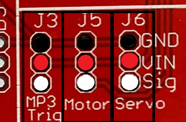
The Master board makes this easy since there are headers and printed labels on the board for easy use.
Put the ESC wire where it says "motor" and the Server with the Servo. If you have a Sparkfun MP3 trigger you can also set up the 3-wires for that too.
Starting and Calibrate
Now we should be able to start testing.
- Plug in the battery
- Press the Playstation button on your controller, the indicator light should be blinking red
- Turn on the ESC (power switch to On)
- The controller red light should stop blinking and be a solid red to show it is connected.
- Servo Test
- Move the thumb stick to the left and right, ensure the steering moves accordingly.
- Motor Test
- Pull the L2 trigger slowly, or quickly, if you want to launch your car, to test the forward throttle
- Release L2 until it stops, then hold the L1 upper trigger button and pull the L2 trigger to test reverse and release again to stop.
- Sound Test ( if you plugged in a speaker )
- Press the D-pad directions and Circle and Cross buttons, each should trigger sound
Sound Boards
Sound Files
SparkFun MP3 Trigger
Requirements
- 1 x micro SD card formatted with FAT32 and enough space to hold your sound files
- 1 x Black Female to Female Dupont Wire
- 1 x Red Female to Female Dupont Wire
- 1 x White Female to Female Dupont Wire
The SparkFun MP3 Trigger board needs three wires between the Shadow Master Control board and the Trigger board, Black (ground), Red (5v vin), and White (signal).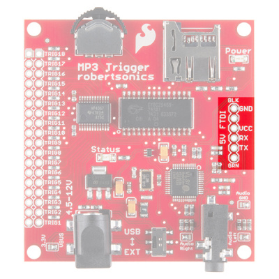
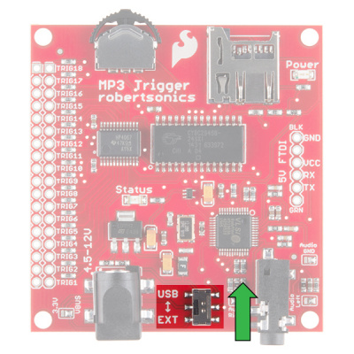
You'll also need to make sure the power selector switch at the bottom or the board is switched to "USB" and not "EXT.
Setting up the sound files
This board uses your average Micro SD card, a large card is not necessary, 1gb to 8 gb is way more than enough for this.
The card should be formatted with FAT32, and the then put your MP3 files onto the SD Card.
The SF board is pretty easy to understand when it comes to how you tell the board what file to play, each file should be renamed to have a 3 digit prefix at the beginning.
Starting with "001" through "018" enables you to order your files and address them, these prefixes also correspond to the 18 trigger pins on the board.
Example Filenames
- 001FileName.mp3 - Without a space
- 002 FileName.mp3 - With a space
Both versions are valid and you can mix formatting.
You won't need to solder to the long row on the left since Shadow is using a Serial connection (via the White wire to RX) and the Shadow code sends the appropriate signal.
The Shadow MSE code already has buttons mapped to certain trigger numbers.
Update the Arduino Sketch
The sketch starts ready for the MDFly board so you'll need to comment out one block of code in the IDE and re-upload the sketch, otherwise you won't get sounds through the trigger board.
Find "Sound Control Settings" near the beginning of the file
// ---------------------------------------------------------------------------------------
// Sound Control Settings
// ---------------------------------------------------------------------------------------
#define MP3TxPin 2 // connect this pin to the MP3 Trigger
#define MP3RxPin 8 // This pin isn't used by the sparkfun MP3 trigger, but is used by the MDFly
//#define Sparkfun // Use the sparkfun MP3 Trigger
#define MDFly // Use the MDFly MP3 Player
//#define RogueRMP3 // Use the Rogue RMP3 PlayerAnd uncomment Sparkfun, and comment out MDFly like this
// ---------------------------------------------------------------------------------------
// Sound Control Settings
// ---------------------------------------------------------------------------------------
#define MP3TxPin 2 // connect this pin to the MP3 Trigger
#define MP3RxPin 8 // This pin isn't used by the sparkfun MP3 trigger, but is used by the MDFly
#define Sparkfun // Use the sparkfun MP3 Trigger
//#define MDFly // Use the MDFly MP3 Player
//#define RogueRMP3 // Use the Rogue RMP3 PlayerThen, find this block under "libraries"
#ifdef MDFly
#include <serMP3.h>
serMP3 MP3(MP3TxPin, MP3RxPin);
#endifAnd comment it out with double forward slashes.
// #ifdef MDFly
// #include <serMP3.h>
// serMP3 MP3(MP3TxPin, MP3RxPin);
// #endifThen re-upload the sketch .
Connect the Shadow and Trigger boards
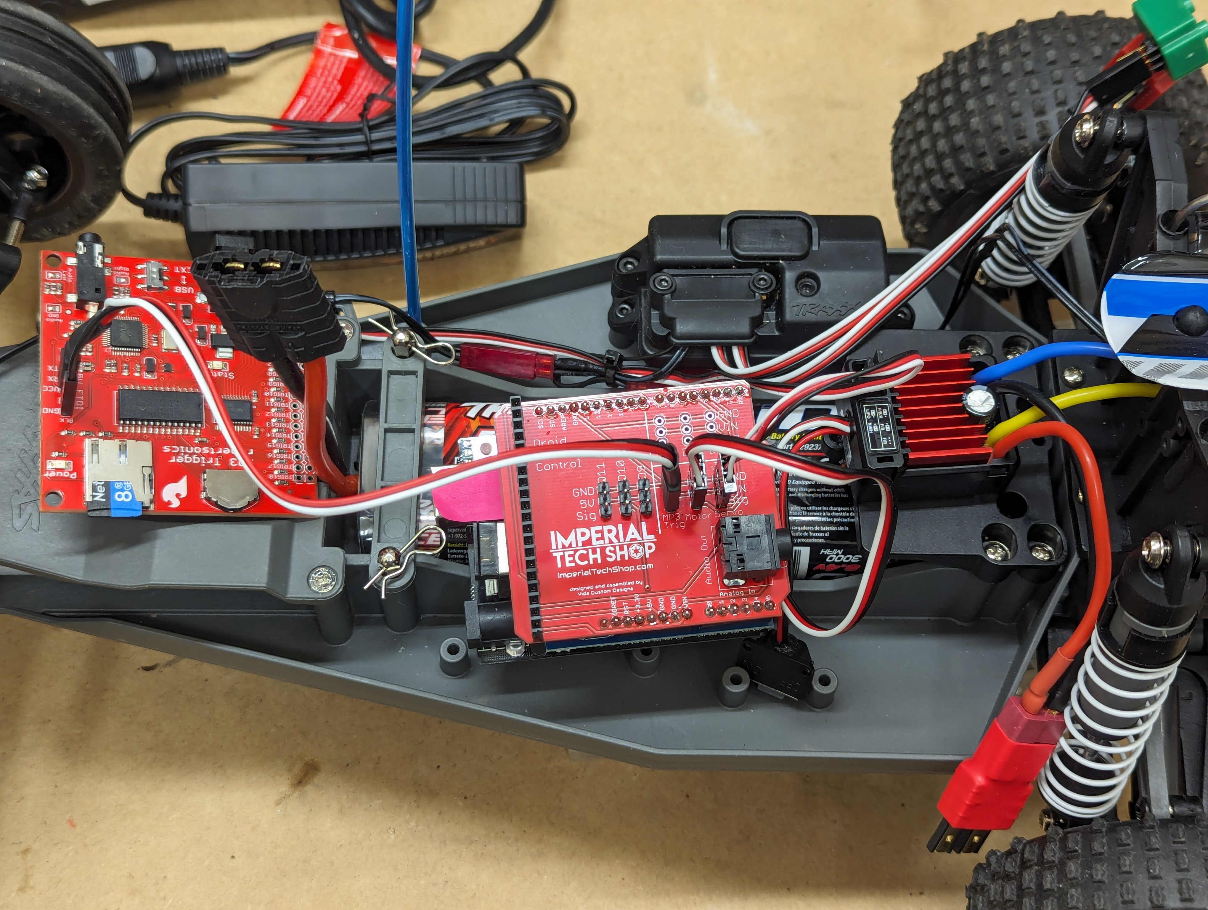
Using a 3-wire setup (Black, Red, White) with Female-to-Female Dupont connectors connecting the pins as follows.
Shadow -> Trigger
- GND -> GND (Black)
- 5V -> VCC (Red)
- SIG -> RCX (White)
Plug your speaker into the stereo port on the MP3 Trigger board and not the Shadow board.
MDFly Sound Board
This is the simpler of the two options that I have tried so far since the Shadow board makes it as simple as "plug and play" with the included header that perfectly fits the MDFly sound board. The Arduino Sketch for SHADOW comes pre-configured for this board so no changes are necessary.
Requirements
- 1 x SD Card (not micro) with enough space and formatted as FAT32. I am using a really old 1 GB Sandisk I had laying around.
Installation
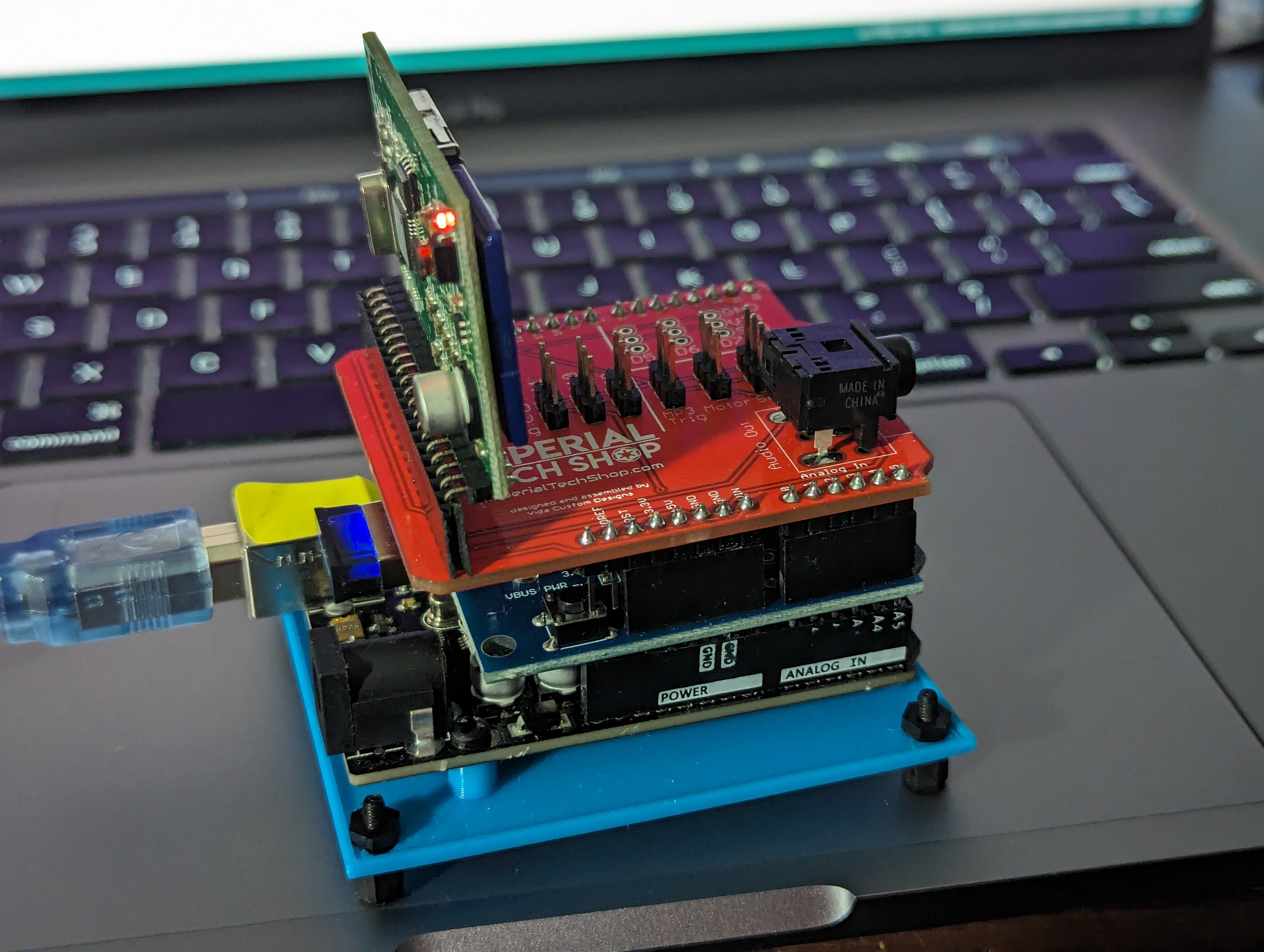
With the Shadow board in front of you with the stereo jack pointing to the right, insert the MDFly board with the SDCard port (bottom) facing the Stereo jack (as below).
Setting up the sound files
Similar to the Sparkfun board, we'll need to rename the files for the MDFly to play the correct sounds for us.
Rename your file to be 3-digits and the extension instead of a prefix based system like the Sparkfun.
Example
- 001.mp3
- 002.mp3
- ...
- 199.mp3
This board supports from 1 to 199 files total but it is severely unlikely you'll need that many.
I'd suggest setting up 7 to 14 files, more is overkill and not possible to trigger properly with one controller.
Update the Arduino Sketch
None, the SHADOW sketch is configured for the MDFly sound board by default!
Button Mapping
- D-pad Up - Sound 001
- D-pad Right - Sound 002
- D-pad Down - Sound 003
- D-pad Left - Random Sound 001-015
- Circle/L2 + D-pad Up - Sound 004
- Cross/L2 + D-pad Right - Sound 005
- Not Available/L2 + D-pad Down - Sound 006
- Not Available/L2 + D-pad Left - Sound 015
- L1 + D-pad Up - Volume Up
- L1 + D-pad Right - Sound 019
- L1 + D-pad Down - Volume Down
- L1 + D-pad Left - Sound 018
Troubleshooting
No Sound
- Common Problems
- Did you load the sound files to an SD Card
- Did you name the files with the appropriate prefixes or names based on the board you are using
- Does your speaker have it's own volume control or Mute
- Is your PS3 move controller paired and connected with your Shadow system.
- Sparkfun
- Make sure you plug the speaker into the MP3 Trigger board and not the Shadow Master board.
- Did you flip the power switch on the board from "EXT" to "USB"
- Did you comment out the MDFly code block shown above.
- MDFly
- Did you name the files appropriately ?
- Is the board installed backwards ?
Hissing noises
Common Ground Interference
A common problem with electronics like this is "common ground interference", since so many other components are connected to the same ground in the system any of them can add some feedback into the ground which subsequently gets fed into your audio. The simple solution is to use an Audio Isolator like this. ( Example )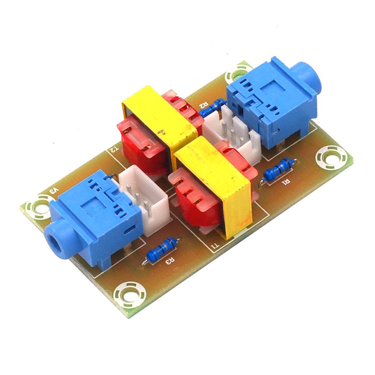 External Interference
Control Map
This page describes the default button mapping for the the SHADOW MSE edition system.
Default (L2 Throttle) Config
Pressing these buttons or pointing the stick in the direction noted without pressing other buttons will trigger the simple action as described on the following cards.


Button |
Action |
Note |
| L1 ( Trigger 1 ) | Engage Reverse | Hold L1 and then L2 when the droid is stopped to move in reverse |
| L2 ( Trigger 2 ) | Throttle Up | This is your "gas" pedal |
| L3 ( Press Stick ) | Random Sound | Plays a random sound file between 1 and 15 |
| Joystick Left | Steer Left | |
| Joystick Right | Steer Right | |
| Joystick Up | --Reserved-- | ** JS Up & Down can be used for throttle after changing the Shadow sketch ** |
| Joystick Down | --Reserved-- | |
| X (cross) | Sound 005 | |
| O (circle) | Sound 006 | |
| D-Pad Up | Sound 001 | |
| D-Pad Right | Sound 002 | |
| D-Pad Down | Sound 003 | |
| D-Pad Left | Sound 004 | |
| PS ( Playstation ) | Power / Pair |
USB Host Shield Troubleshooting
Soldering is usually required.
The common USB-A host shield available for purchase right now (as of 2023) requires varying levels of soldering before it will work. The intent is to allow the end-user to decide some settings based on the specific use-case they are building for. In practice though, nearly everyone have the same settings requirements.
Save yourself time and buy this board instead ( buy here )
Identifying your board
Ok, so you want to know if the USB-A shield you have requires soldering, it probably does.
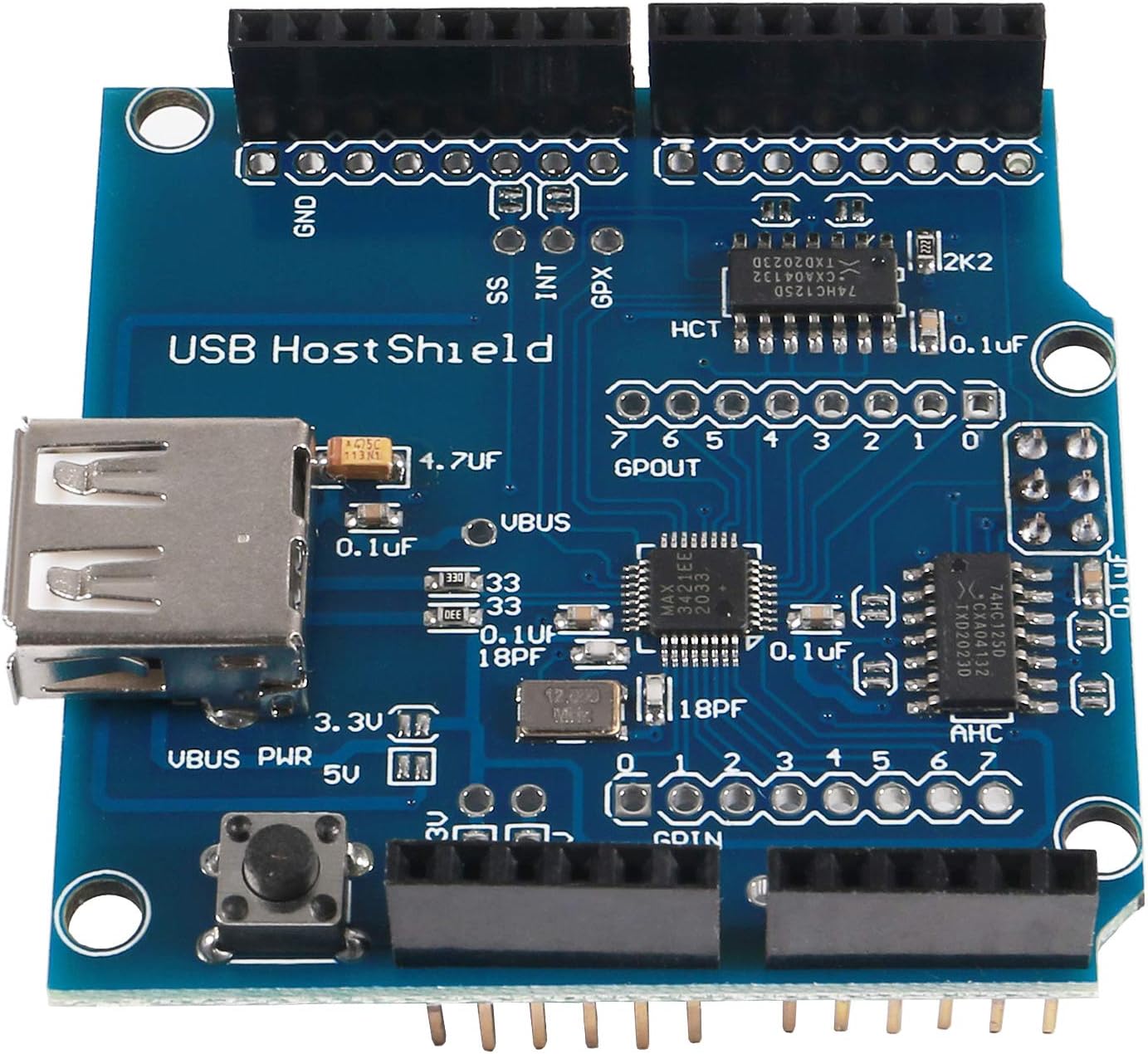
But what if your really uncertain or want to make absolutely sure ? Fine, is your board laid out like the one below ?
The color of the shield doesn't matter, it's the layout of the items on the shield that matters !
Common Board Colors: Blue, White
Configuring the Board
This board provides several power settings between 3.3 and 5 volts. For S.H.A.D.O.W. For our purpose, we will enable both 3.3V and 5V input but only set the 5V VBUS power control.
If it smells like chicken cooking, get your fingers off the hot end
Where do i put the solder if not my hand ? I'll show you! You'll want to "bridge" the two little separate bars within the 3.3V and 5V ground on the left side and ONLY the 5V pads for VBUS power. When you are done your board should look like below.
Be careful! Only bridge the two pads within the boxes that are circled in RED below!
Solder Steps
- Bridge 3.3V Input
- Bridge 5V Input
- Bridge 5V VBUS PWR
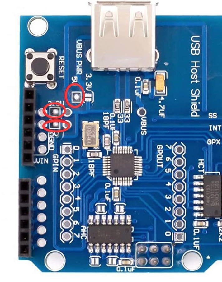
At this point you should be able to boot your Arduino with the USB shield installed and not get the dreaded 'OSC did not start' error message.
Common Manufacturing Error
There is a mistake that hit nearly all boards on the market at this time (2023). On the board there are two chips that look identical. One on the bottom (when the USB port is pointed up) and one on the right side. On the board itself these are labeled "AHC" and "HC" respectively.
So, what's the problem ? They are actually identical chips when they are supposed to be two different versions of similar chips.
- The bottom chip should read 74AHC125D
- The right chip should read 74HC125D
The problem comes when BOTH chips are 74HC125D instead of one each as above.
The HC chip is designed to handle 3.3V while the AHC is designed to handle 5V so any USB devices that are not LE will not work until you replace the "bottom" chip marked "AHC" on the board. Unfortunately this means everything we need for Shadow will not work until this is fixed.
How to fix this
You will need to replace the bottom chip with an appropriate 74AHC125D chip.
Example 74AHC125D replacement ( Mouser 1 or Mouser 2 )
A good de-soldering braid and pump will very helpful for this delicate procedure.
De-solder and solder the new chip onto the board and the shield should start working properly.
Or, contact the seller and try to get them to send you a correct board. Most likely ? You'll end up going through one or two exchanges and have to make the replacement of the chip yourself.
Example Video by Steve @ Imperial Light and Magic
Correct Chip Example
If your board has the correct chip it will look like this, notice it says "74AHC.." and not "74HC.."

Troubleshooting
-
OSC did not start
- If you are seeing this, did you follow the instructions above ? Probably not.
- Double check that all pins for the USB Shield are properly seated into the Arduino board, sometimes a pin will "escape" and not sit in a header so you'll also get these failures.
-
Library starts but USB devices don't connect when plugged in
- Triple check that the 3.3V and 5V inputs and 5V VBUS are soldered properly
- Have you checked the 2 bigger chips on your board to see if you are a victim of the Common Manufacturing Error ?
-
Bluetooth Adapter has a flashing blue light
- So, you have a USB shield with the proper 74ACH125D chip, reset, and now the adapter is lighting up, but it's flashing slowly and you aren't seeing the appropriate output, now what do you do ?
- Ask yourself this, did you, in your attempts to get your shield working upgrade the USB_HOST_SHIELD library by grabbing the 2.0 library from Github ? If your answer is "YES" or "Possibly", "I don't know", or, "I blanked out for 30 minutes and here we are" then you need to just delete that from the Arduino Libraries folder and re-install the USB_HOST_SHIELD library from the SHADOW folder. Shut down the IDE, restart it, then upload the sketch again.
TL:DR Checklist
Arduino + Controller Setup
- Install the Arduino IDE (if not already installed)
- Download the SHADOW Arduino sketch and libraries ( link )
- Extract the folder
- Install libraries from the Shadow folder to the Arduino Libraries folder
- For Windows, this will be under
Documents / Arduino / librariesby default - Copy these folders
- MP3Trigger ( Sparkfun MP3 Trigger board )
- serMP3 ( MdFly MP3 board )
- USB_Host_Shield
- For Windows, this will be under
- Open the sketch in the IDE (
Shadow / Shadow.ino) - Set up the USB Shield ( see here )
- Connect your USB Shield and Arduino
- Connect your Arduino to your computer using a USB-A to USB-B cable
- Upload the sketch using the Arduino IDE
- Click on "Verify"
- Click on "Upload"
- Connect to the Arduino using the Serial Monitor
- Tools -> Serial Monitor
- Select 115200 Baud
- Check the output
- Unplug the Arduino
- Plug in the Bluetooth USB adapter
- Plug the Arduino back into the Computer
- Check the Serial Monitor
- Unplug the Bluetooth Adapter
- Plug the PS3 Move controller into the shield using a USB-A to USB-Mini cable
- Get the Bluetooth MAC address for the controller form the Monitor
- With the controller unplugged, press the Playstation button to start pairing
- Update the PS3MoveNavigatonPrimaryMAC variable in the Shadow sketch using the IDE with the MAC from the controller
- Re-place the Bluetooth Adapter
- Re-Upload the sketch after saving