
Arduino USB Host Shield
Soldering is usually required.
The common USB-A host shield available for purchase right now (as of 2023) requires varying levels of soldering before it will work. The intent is to allow the end-user to decide some settings based on the specific use-case they are building for. In practice though, nearly everyone have the same settings requirements.
Identifying your board
Ok, so you want to know if the USB-A shield you have requires soldering, it probably does.
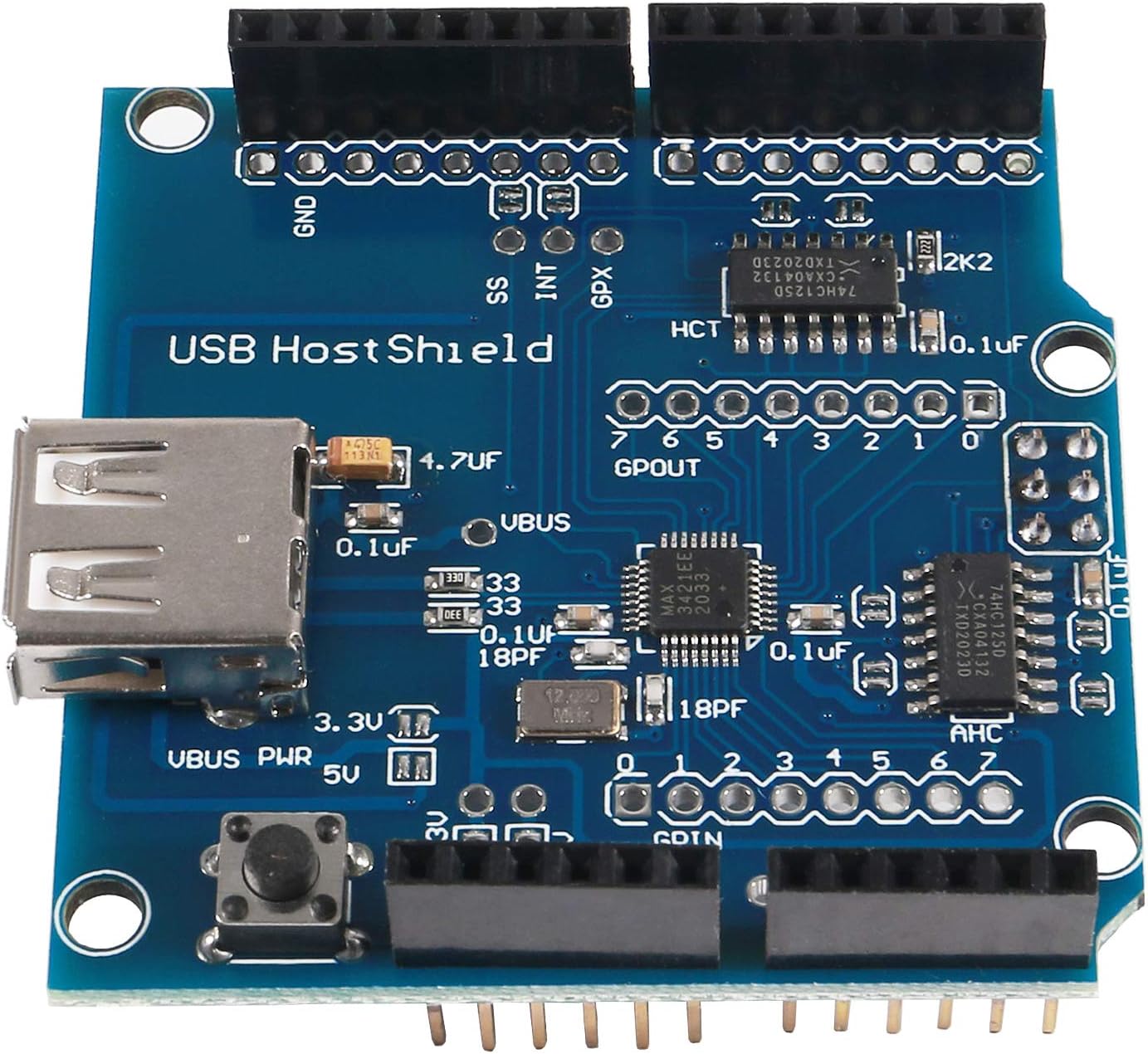
But what if your really uncertain or want to make absolutely sure ? Fine, is your board laid out like the one below ?
The color of the shield doesn't matter, it's the layout of the items on the shield that matters !
Common Board Colors: Blue, White
Configuring the Board
This board provides several power settings between 3.3 and 5 volts. For S.H.A.D.O.W. For our purpose, we will enable both 3.3V and 5V input but only set the 5V VBUS power control.
If it smells like chicken cooking, get your fingers off the hot end
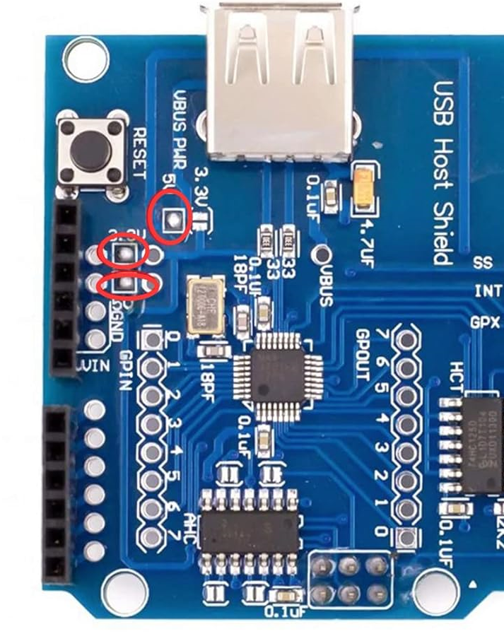
Where do i put the solder if not my hand ? I'll show you! You'll want to "bridge" the two little separate bars within the 3.3V and 5V ground on the left side and ONLY the 5V pads for VBUS power. When you are done your board should look like below.
Be careful! Only bridge the two pads within the boxes that are circled in RED below!
Solder Steps
- 3.3V Input
- 5V Input
- 5V VBUS PWR
At this point you should be able to boot your Arduino with the USB shield installed and not get the dreaded 'OSC did not start' error message.
Common Manufacturing Error
There is a mistake that hit nearly all boards on the market at this time (2023). On the board there are two chips that look identical. One on the bottom (when the USB port is pointed up) and one on the right side. On the board itself these are labeled "AHC" and "HC" respectively.
So, what's the problem ? They are actually identical chips when they are supposed to be two different versions of similar chips.
- The bottom chip should read 74AHC125D
- The right chip should read 74HC125D
The problem comes when BOTH chips are 74HC125D instead of one each as above.
The HC chip is designed to handle 3.3V while the AHC is designed to handle 5V so any USB devices that are not LE will not work until you replace the "bottom" chip marked "AHC" on the board.
How to fix this
You will need to replace the bottom chip with an appropriate 74AHC125D chip.
Example 74AHC125D replacement ( Mouser )
De-solder and solder the new chip onto the board and the shield should start working properly.
Or, contact the seller and try to get them to send you a correct board. Most likely ? You'll end up going through one or two exchanges and have to make the replacement of the chip yourself.
Troubleshooting
-
OSC did not start
- If you are seeing this, did you follow the instructions above ? Probably not.
-
Library starts but USB devices don't connect when plugged in
- Triple check that the 3.3V and 5V inputs and 5V VBUS are soldered properly
- Have you checked the 2 bigger chips on your board to see if you are a victim of the Common Manufacturing Error ?